Meeting the needs of complex peripheral artery disease: The devices and decisions needed for optimizing outcomes
IVUS for GORE® TIGRIS® Vascular Stent placement during knee flexion
Intravascular ultrasound confirms the shape-maintaining abilities of a GORE® TIGRIS® Vascular Stent placed in the popliteal artery during leg flexion.
Prof. J. Ian Spark, MD, FRACS, FRCS
Richard Allan, DMU, BHIthSc (Hons)
The superficial femoral artery (SFA) and popliteal artery are a hostile environment for endovascular treatment due to high rates of more advanced atherosclerotic disease and a complex range of forces during normal leg movements.1-3 Although stenting has been shown to be superior to plain angioplasty, restenosis rates are still unacceptably high.4,5 Conventional nitinol stents are not well suited to these conditions due to their relative rigidity and lack of compliance, which result in an increased risk of kinking and fracture.6,7 Mimetic stents are designed to mimic the flexibility found in the SFA and popliteal arteries and manage the extreme forces routinely found in these arteries. A number of mimetic stents are now available that utilize a range of design solutions, providing alternative options for the interventionalist.
The GORE® TIGRIS® Vascular Stent is a hybrid design that provides greater flexibility by combining a nitinol wire frame and a heparin-bonded interconnecting expanded polytetrafluoroethylene lattice. Results of studies evaluating the GORE TIGRIS Vascular Stent have been encouraging, with 90% freedom from target lesion revascularization (TLR) at 12 months in shorter lesions,8 86% freedom from TLR at 12 months in a more high-risk population (70% of patients with critical limb ischemia [CLI], 74% with occlusions, and a mean lesion length of 114 mm),9 and no reported cases of stent fracture.10
We suspect the stent’s kink resistance plays an underreported role in these positive clinical outcomes. Intravascular ultrasound (IVUS) has been shown to be superior to digital subtraction angiography (DSA) in assessing vessel and stent characteristics11-17 and is therefore an ideal imaging modality to assess the stent’s ability to maintain its shape when subjected to knee flexion. As far as we are aware, this is the first report of IVUS evaluation of the performance of a GORE TIGRIS Vascular Stent in the popliteal artery. Key parameters to assess stent performance are maintenance of normal stent lumen and shape during knee flexion. Reduction in stent lumen area and eccentric lumen shape are associated with an increased risk of in-stent restenosis (ISR) in the coronary arteries,18 and the MUSIC quantitative criteria have been created to identify inadequate stent expansion in the coronary arteries.19 The stent lumen area ratio (minimum stent lumen/mean reference lumen) and stent lumen symmetry ratio (minimum stent lumen diameter/maximum stent lumen diameter) can be used to provide objective assessment of the adequacy of stent deployment. It should be noted that there are no validated criteria to evaluate stent expansion using IVUS in the peripheral arteries, although a recent retrospective analysis suggests that a stent lumen area of < 15.5 mm2 may be associated with increased incidence of restenosis.20
CASE PRESENTATION
A 68-year-old man, a former smoker with a past medical history of ischemic heart disease, hypertension, and type 2 diabetes, presented with a deteriorating left ankle ulcer, SFA/popliteal stenotic disease on duplex ultrasound (peak systolic velocity [PSV], 322 cm/s), and extensive severe calcific disease in the distal SFA and P1/2 popliteal segments on CTA (Figure 1).
Initial diagnostic angiography and IVUS confirmed diffuse disease with extensive calcification and multiple areas of stenosis in the distal SFA and the P1/2 segments of the popliteal artery. Reference vessel diameters (RVDs) were obtained using DSA quantitative vessel analysis (RVD, 5 mm) and IVUS (RVD, 5.6 mm), and 6 mm balloons were used based on the IVUS lumen measurements. The vessel was treated using a standardized angioplasty technique of 3 minute inflation with a 6 mm ABBOTT® ARMADA 35 LL Percutaneous Transluminal Angioplasty Catheter, followed by a 1 minute inflation of 6 mm MEDTRONIC IN.PACT® Admiral Drug-Coated Balloons, with a 10 mm overlap between balloons over a 280 mm length from the mid-SFA to just below the knee joint. The use of a long inflation time for plain balloon angioplasty has been recommended to reduce the incidence of flow-limiting dissection and residual stenosis.21-24 We believe that the additional time taken for a more thorough initial vessel preparation is rewarded with a lesser need for repeated dilatation, particularly in heavily calcified arteries.
Postangioplasty angiography and IVUS revealed residual stenosis, and IVUS imaging revealed that all landing zones had significant plaque burden between the residual stenotic lesions. Therefore, the entire length of the treated vessel was stented. A 280 mm length of vessel was treated with three stents: 6 x 100 mm and 6 x 80 mm GORE TIGRIS Vascular Stents and a 6 x 120 mm BARD® LIFESTENT® Vascular Stent System (deployed from above the adductor canal to the mid SFA), with 10 mm of overlap between stents. BARD® LIFESTENT® Vascular Stent System was used in the segment proximal to the adductor canal because there were no appropriately sized GORE TIGRIS Vascular Stents available at the time of treatment. Postdeployment dilatation of the stents was performed with 6 mm plain balloons.
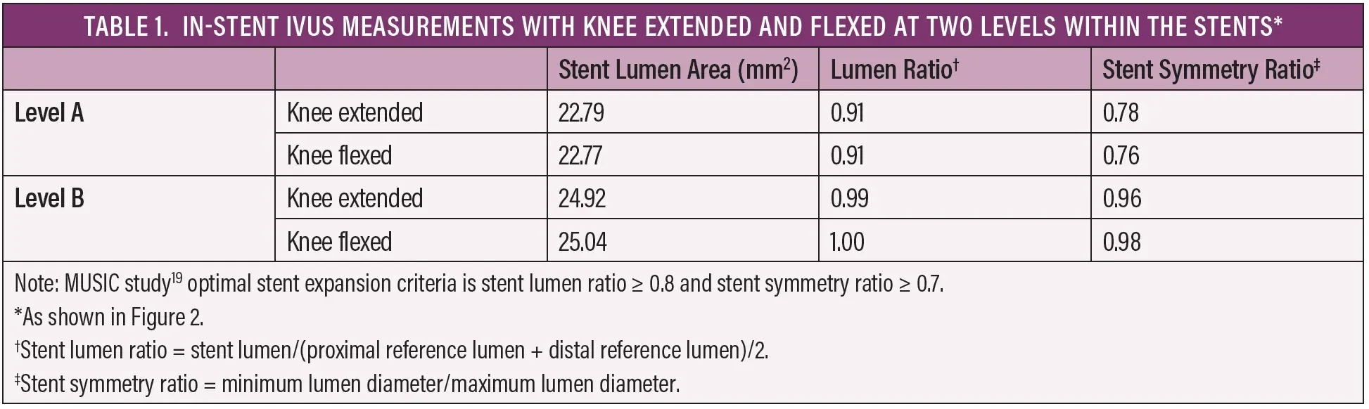
Postdeployment angiography performed with the knee extended and in flexion showed no kinking or stenosis (Figure 2). IVUS was then performed with the knee extended and flexed, and measurements of the stent lumen were obtained at 5 mm increments. Stent lumen area and stent lumen symmetry were analyzed using the MUSIC study criteria (Table 1).19 IVUS with the leg extended showed good results with no areas of underexpansion and no change seen during knee flexion. In addition, the stent lumen was > 15.5 mm2 throughout the stented segment. Lumen area and stent symmetry were optimal with the knee extended and flexed (Figures 3 and 4), with a circular lumen area apparent through most of the stent length (Figures 3B and 4B). There was an area of mildly eccentric lumen (Figures 3A and 4A) in the area of maximum calcification. This was most likely due to the significant calcification (Figure 1) rather than artery movement, as the lumen shape was unchanged with knee flexion. The lumen shape was well within the acceptable range and demonstrated the stent’s ability to resist compression by a highly calcified lesion.
There were no immediate postprocedural complications, and follow-up to date at 6 weeks has been normal (duplex ultrasound PSV ratio was 1.3 at the 6 week surveillance scan).
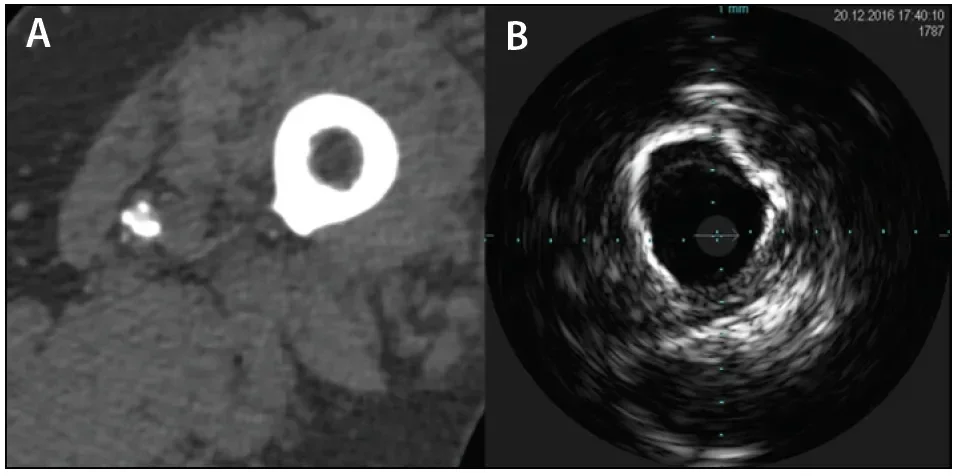
Figure 1. CTA image showing a calcified artery at the adductor canal (A). IVUS image at the same level showing calcification extending around at least 270° of the circumference, consistent with a grade 3B lesion as described by Fanelli et al24 (B).
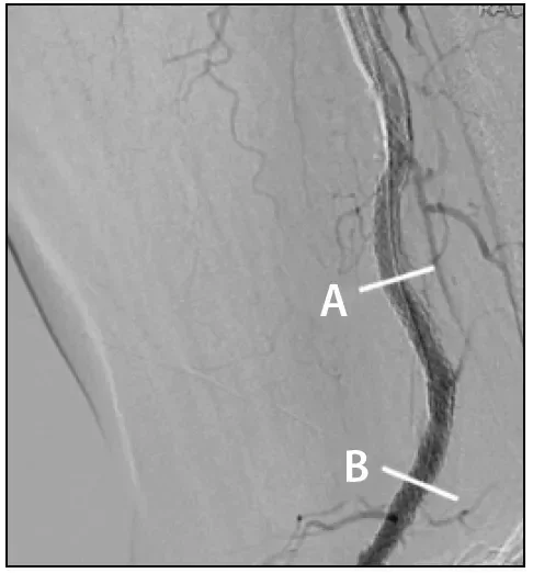
Figure 2. DSA image of the popliteal artery with the knee flexed after GORE® TIGRIS® stent deployment. The bars labeled A and B indicate the levels of the IVUS images featured in Figures 3 and 4.
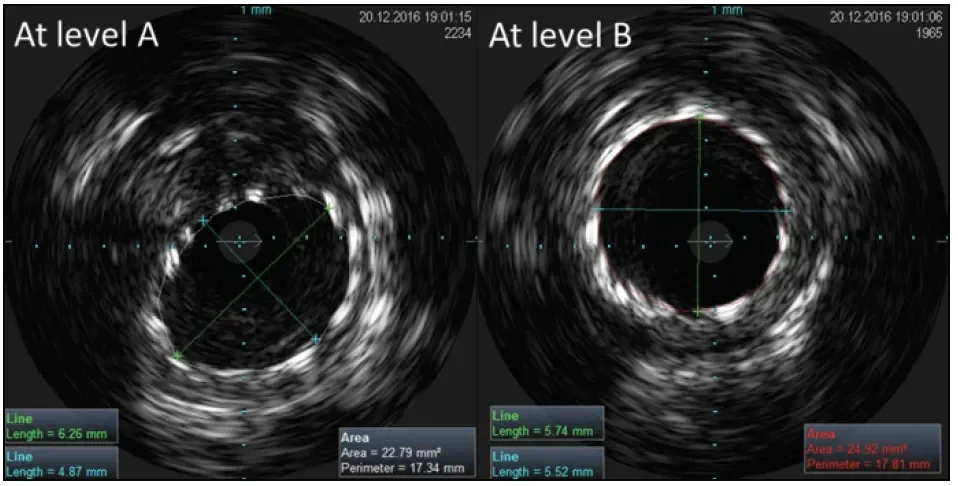
Figure 3. IVUS images of the GORE® TIGRIS® Vascular Stent at levels A and B as indicated in Figure 2 with the knee extended. Image A shows the area of minimum stent lumen and maximum eccentricity, and image B is representative of stent expansion seen through most of the stented artery. See Table 1 for the measurements and ratios at these levels.
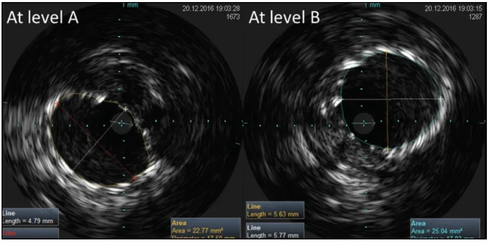
Figure 4. IVUS images of a GORE® TIGRIS® Vascular Stent at levels A and B as indicated in Figure 2 with the knee flexed. No change is seen at these levels compared to the knee in extension (Figure 3). See Table 1 for the measurements and ratios at these levels.
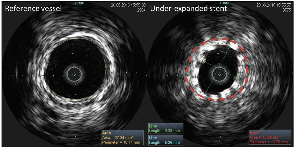
Figure 5. IVUS images of a conventional nitinol stent in the distal SFA demonstrating an under-expanded stent (right) in comparison to the proximal reference vessel (left). The red dashed line indicates the reference lumen size (27.3 mm2) that should have been achieved if optimal stent expansion had occurred. Note the significantly reduced stent lumen (stent lumen area, 13.8 mm2; stent lumen ratio, 0.51) and eccentric stent lumen (stent symmetry ratio, 0.64).
DISCUSSION
In this case, using objective criteria, IVUS demonstrated that the GORE TIGRIS Vascular Stent maintained good lumen size and symmetry, with good stent apposition, in a highly calcified popliteal artery. The flexible design of the GORE TIGRIS Vascular Stent coped easily with the range of forces applied to it during flexion with no deformation, kinking, or compression during knee flexion. Figure 5 shows a conventional nitinol stent placed using the same technique as in
the case presentation in a patient with similar disease to illustrate how a poorly expanded, eccentric stent appears on IVUS. IVUS also allowed better matching of the balloon and stent size to vessel dimensions and identified disease-free areas for landing the proximal and distal ends of the stents.
Data From 42 Patients Treated With the GORE TIGRIS Vascular Stent
We have used the GORE TIGRIS Vascular Stent to treat 42 patients with complex lesions (CLI in 61% of cases, occlusion in 53% of cases, popliteal location in 82% of cases, and a mean lesion length of 122 mm), with 12 month freedom from clinically driven TLR of 93% (unpublished data). We believe our excellent clinical outcomes with the GORE TIGRIS Vascular Stent are related to its flexibility and kink resistance, more accurate lesion assessment by IVUS, and the long and careful vessel preparation used prior to stent placement. The addition of IVUS allows for optimum sizing of the stent, and for treatment of the entire diseased segment.
It is clear that IVUS provides more accurate measurement of vessel lumen and lesion length and better assesses the adequacy of stent placement compared to DSA. A combined imaging approach provides a more comprehensive assessment of stent performance than angiography alone. Trials of coronary endovascular devices have required IVUS assessment as part of study design for some time, and it is time for peripheral vascular trials to follow suit. IVUS assessment during flexion may be prudent in trials of popliteal artery stenting to identify whether kinking or changes to lumen shape are occurring under conditions of maximum stress.
CONCLUSION
In this case, the GORE TIGRIS Vascular Stent performed well in a calcified popliteal artery. The combination of the GORE TIGRIS Vascular Stent, IVUS imaging, and careful and rigorous endovascular technique can deliver excellent results in one of the most hostile vascular environments.
- Wood NB, Zhao SZ, Zambanini A, et al. Curvature and tortuosity of the superficial femoral artery: a possible risk factor for peripheral arterial disease. J Appl Physiol (1985). 2006;101:1412-1418.
- Wensing PJ, Scholten FG, Buijs PC, et al. Arterial tortuosity in the femoropopliteal region during knee flexion: a magnetic resonance angiographic study. J Anat. 1995;187(pt 1):133-139.
- Klein AJ, Chen SJ, Messenger JC, et al. Quantitative assessment of the conformational change in the femoropopliteal artery with leg movement. Catheter Cardiovasc Interv. 2009;74:787-798.
- Laird JR, Katzen BT, Scheinert D, et al. Nitinol stent implantation versus balloon angioplasty for lesions in the superficial femoral artery and proximal popliteal artery: twelve-month results from the RESILIENT randomized trial. Circ Cardiovasc Interv. 2010;3:267-276.
- Schillinger M, Sabeti S, Loewe C, et al. Balloon angioplasty versus implantation of nitinol stents in the superficial femoral artery. N Engl J Med. 2006;354:1879-1888.
- Arena FJ. Arterial kink and damage in normal segments of the superficial femoral and popliteal arteries abutting nitinol stents—a common cause of late occlusion and restenosis? A single-center experience. J Invasive Cardiol. 2005;17:482-486.
- Scheinert D, Scheinert S, Sax J, et al. Prevalence and clinical impact of stent fractures after femoropopliteal stenting. J Am Coll Cardiol. 2005;45:312-315.
- Piorkowski M, Freitas B, Steiner S, et al. Twelve-month experience with the GORE® TIGRIS® vascular stent in the superficial femoral and popliteal arteries. J Cardiovasc Surg (Torino). 2015;56:89-95.
- Parthipun A, Diamantopoulos A, Kitrou P, et al. Use of a new hybrid heparin-bonded nitinol ring stent in the popliteal artery: procedural and mid-term clinical and anatomical outcomes. Cardiovasc Intervent Radiol. 2015;38:846-854.
- Laird J. Novel nitinol stent for long lesions in the superficial femoral artery and proximal popliteal artery: 24-month results from the TIGRIS randomized trial. Presented at Vascular InterVentional Advances Conference (VIVA) 2016; September 18–22, 2016; Las Vegas, Nevada.
- Tabbara M, White R, Cavaye D, Kopchok G. In vivo human comparison of intravascular ultrasonography and angiography. J Vasc Surg. 1991;14:496-502.
- Nissen SE, Gurley JC, Grines CL, et al. Intravascular ultrasound assessment of lumen size and wall morphology in normal subjects and patients with coronary artery disease. Circulation. 1991;84:1087-1099.
- Arthurs ZM, Bishop PD, Feiten LE, et al. Evaluation of peripheral atherosclerosis: a comparative analysis of angiography and intravascular ultrasound imaging. J Vasc Surg. 2010;51:933-938.
- Cooper BZ, Kirwin JD, Panetta TF, et al. Accuracy of intravascular ultrasound for diameter measurement of phantom arteries. J Surg Res. 2001;100:99-105.
- Briguori C, Tobis J, Nishida T, et al. Discrepancy between angiography and intravascular ultrasound when analysing small coronary arteries. Eur Heart J. 2002;23:247-254.
- Schwarzenberg H, Müller-Hülsbeck S, Gluer CC, et al. Restenosis of peripheral stents and stent grafts as revealed by intravascular sonography: in vivo comparison with angiography. AJR Am J Roentgenol. 1998;170:1181-1185.
- van Sambeek MR, Qureshi A, van Lankeren W, et al. Discrepancy between stent deployment and balloon size used assessed by intravascular ultrasound. Eur J Vasc Endovasc Surg. 1998;15:57-61.
- McDaniel MC, Eshtehardi P, Sawaya FJ, et al. Contemporary clinical applications of coronary intravascular ultrasound. JACC Cardiovasc Interv. 2011;4:1155-1167.
- de Jaegere P, Mudra H, Figulla H, et al. Intravascular ultrasound-guided optimized stent deployment: Immediate and 6 months clinical and angiographic results from the multicenter ultrasound stenting in coronaries study (MUSIC study). Eur Heart J. 1998;19:1214-1223.
- Miki K, Fujii K, Kawasaki D, et al. Intravascular ultrasound-derived stent dimensions as predictors of angiographic restenosis following nitinol stent implantation in the superficial femoral artery. J Endovasc Ther. 2016;23:424-432.
- Zorger N, Manke C, Lenhart M, et al. Peripheral arterial balloon angioplasty: effect of short versus long balloon inflation times on the morphologic results. J Vasc Interv Radiol. 2002;13:355-359.
- Eltchaninoff H, Cribier A, Koning R, et al. Effects of prolonged sequential balloon inflations on results of coronary angioplasty. Am J Cardiol. 1996;77:1062-1066.
- Katsanos K, Tepe G, Tsetis D, Fanelli F. Standards of practice for superficial femoral and popliteal artery angioplasty and stenting. Cardiovasc Intervent Radiol. 2014;37:592-603.
- Fanelli F, Cannavale A, Gazzetti M, et al. Calcium burden assessment and impact on drug-eluting balloons in peripheral arterial disease. Cardiovasc Intervent Radiol. 2014;37:898-907.
Products listed may not be available in all markets.
See all products by region:

This product has been discontinued.

Endovascular Today February 2018 Supplement
Meeting the Needs of Complex Peripheral Artery Disease
Prof. J. Ian Spark, MD, FRACS, FRCS
Department of Vascular and Endovascular Surgery Flinders University and Flinders Medical Centre
Adelaide, Australia
Disclosures: None.
Richard Allan, DMU, BHIthSc (Hons)
Department of Vascular and Endovascular Surgery Flinders University and Flinders Medical Centre
Adelaide, Australia
Disclosures: None.